
 EN
EN
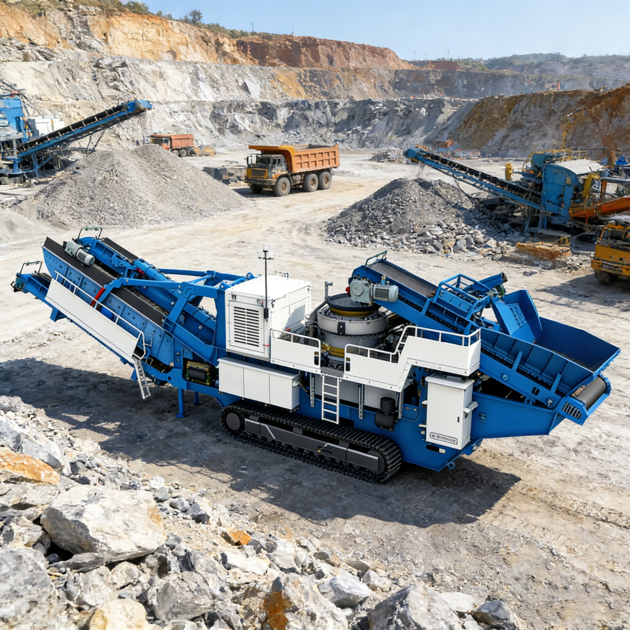
Learn about horizontal shaft impact crusher components—rotor assembly, blow bars, impact plates, and housing. Expert guide on material selection, dynamic balance, and maintenance strategies for maximum uptime.
Introduction
The horizontal shaft impact crusher (HSI crusher) is one of the most widely used crushing machines in aggregate production, mining, and concrete recycling. Its ability to deliver high reduction ratios and produce cubical-shaped products makes it indispensable in modern processing operations.
But what makes an HSI crusher perform reliably under extreme conditions? The answer lies in understanding its key structural components—from the high-speed rotor assembly to the wear-resistant blow bars and impact plates. This guide breaks down each component, explains how material selection affects durability, and provides actionable maintenance strategies to prevent costly failures.
What You’ll Learn:
The role of each major component in the HSI crusher
How dynamic balance design prevents catastrophic vibration
Material selection strategies for blow bars and impact plates
Common structural failures and how to prevent them
Proactive maintenance techniques for extended service life
1. Rotor Assembly: The Heart of the HSI Crusher
The rotor assembly is the core component of any horizontal shaft impact crusher. It delivers the kinetic energy necessary for size reduction through high-speed rotation.
1.1 Structural Composition
A typical HSI rotor consists of:
A heavy central shaft machined from high-strength forged steel
Multiple rotor discs mounted on the shaft
Blow bars secured by wedge locking systems
Wear plates protecting the disc faces
The rotor can weigh several tons and rotate at tip speeds exceeding 70 m/s.
1.2 Dynamic Balance Design
Dynamic balance is not optional—it is engineered from the outset. Even minor mass asymmetry at these speeds can generate destructive vibration that:
Accelerates bearing wear exponentially
Transmits fatigue loads to the frame
Potentially initiates structural cracks
Manufacturers address this through:
Precision machining of all mating surfaces
Strategic addition of counterweights
Two-plane balance verification on test rigs
⚠️ Critical Note: After blow bar changes, operators must follow strict placement and weighting protocols. Reversible rotor systems can double usable wear edges, but only if replacement procedures maintain balance integrity.
1.3 Performance Impact
A properly balanced rotor ensures:
Smooth power transfer from the drive motor
Consistent particle shape output
Operation within safe vibration limits throughout service life
2. Blow Bars and Impact Plates: Material Selection for Durability
Blow bars and impact plates are the primary wear components in an HSI crusher. They endure severe abrasion and high-energy impact with every rotation.
2.1 Blow Bars: The Striking Force
Blow bars are mounted radially on the rotor and deliver the impacting force to the feed material. Material selection is the single most important factor determining wear life and maintenance cost.
| Material Type | Best Application | Key Advantage |
|---|---|---|
| High-Manganese Austenitic Steel | Softer, less abrasive feed | Work-hardening capability |
| Martensitic Chromium-Iron Alloys | Highly abrasive materials | Superior abrasion resistance via hard carbide network |
| Ceramic-Matrix Composites | Extreme-duty, gouging wear | Ceramic inserts bonded to tough steel core |
2.2 Impact Plates: The Crushing Chamber Walls
Impact plates define the crushing chamber and serve as the anvil against which material shatters. Key design considerations include:
Adjustable gap between impact plates and rotor tip enables precise control over final product size
Symmetrical, solid designs allow parts to be flipped before full wear-through, maximizing service life
Even force distribution across wearing surfaces extends component longevity
2.3 Geometry Matters
Adjusting the feed angle by just 5° can extend blow bar life by up to 18% in limestone applications, according to high-speed video analysis from leading OEMs. Proper chamber geometry distributes wear evenly, minimizing downtime for rotation or replacement.
3. Crusher Housing, Feed Inlet, and Discharge Configuration
The housing, feed inlet, and discharge system work together to contain the crushing process while enabling precise product control.
3.1 Housing Design
The housing fully encloses the crushing process, providing structural support and containing fly-rock. It is fabricated from:
Thick, welded steel plate
Replaceable wear liners at high-impact zones
Reinforced mounting points to withstand repeated shock loading
3.2 Feed Inlet Engineering
The feed inlet is engineered to direct incoming material onto the rotor's blow bars—not the housing. Its shape and angle regulate flow, supporting a steady, choke-free feed that maximizes throughput.
3.3 Discharge Configuration
On the discharge side, configuration governs final product grading:
Hydraulically or mechanically adjustable openings alter clearance between rotor and impact plates
Adjustable residence time tunes particle size distribution
Secondary grinding paths recirculate oversize particles, enhancing cubicity
Together, these three systems allow the crusher to be tuned for diverse applications—without compromising structural integrity.
4. Crusher Kinematics and Structural Design
4.1 Rotor Speed and Capacity
Rotor speed directly determines centrifugal force—and thus kinetic energy—imparted to feed material. As RPM increases:
| Speed Change | Throughput Impact | Bearing Load Impact |
|---|---|---|
| +20% speed increase | +15% processing volume | +30% bearing load |
Source: Mining Engineering, 2021
Higher velocity improves reduction ratios but intensifies dynamic loads. Engineers must:
Size rotor shafts appropriately
Select bearing arrangements with safety margins
Stiffen frames to keep natural frequencies well above operating speeds
4.2 Material Trajectory and Wear Distribution
Material trajectory inside the chamber—shaped by rotor speed, blow-bar angle, and apron curvature—dictates where and how particles strike wear surfaces. Poorly optimized paths concentrate impact energy in localized zones, accelerating erosion.
Optimization strategies:
Adjust feed angle to distribute wear evenly
Install replaceable liner plates at high-impact locations
Use chamber geometry to minimize stress cycles on the housing
5. Common Structural Failures and Prevention
5.1 Three Major Failure Modes
| Failure Type | Primary Cause | Consequence |
|---|---|---|
| Blow Bar Fracture | Cumulative impact fatigue; tramp metal entry | Sudden catastrophic failure |
| Rotor Deformation | Chronic imbalance; operation beyond rated speed | Distorted disc spacing; vibration; bearing overload |
| Housing Fatigue | Thousands of cyclic shock loads per hour | Cracks near weld seams and mounting points |
According to aggregated quarry maintenance data (2023), undetected blow-bar wear accelerates housing damage rates by up to 30% when scheduled rotation or replacement is deferred.
5.2 Proactive Maintenance Strategies
Reinforcement Techniques:
Apply hardfacing alloys to high-impact zones
Upgrade to heat-treated martensitic steel blow bars
Install sacrificial wear plates at critical locations
Condition Monitoring:
Integrate vibration sensors to monitor rotor dynamics
Use thermal imaging to track bearing temperatures in real time
Trigger alerts before catastrophic failure occurs
Adaptive Maintenance:
Replace wear parts based on measured wear trends rather than fixed intervals
Cut unplanned downtime by anticipating replacement needs
Complement hardware upgrades with operator training to recognize early performance shifts
6. Frequently Asked Questions
Q: What is the purpose of the rotor assembly in a horizontal shaft impact crusher?
A: The rotor assembly is the heart of the crusher, delivering kinetic energy necessary for size reduction through high-speed rotation. It comprises a central shaft, discs, and wedge-secured blow bars.
Q: How do material selection and geometry impact wear life for blow bars and plates?
A: Material selection—such as high-manganese steel or ceramic-matrix composites—directly impacts wear resistance. Symmetrical designs allow flipping parts before full wear-through, extending service life.
Q: What indicators suggest that blow bar wear is causing housing fatigue?
A: Cracks near weld seams and mounting points are common symptoms. Accelerated damage may occur if blow bar rotation or replacement is deferred.
Q: How can crusher kinematics optimize operational performance?
A: Adjusting rotor speed and feed angle ensures even distribution of impact energy and wear, improving reduction ratios, component longevity, and throughput capacity.
Q: What maintenance strategies help prevent structural failures in crushers?
A: Proactive steps include targeted reinforcement, vibration monitoring, thermal imaging, adaptive maintenance schedules, and operator training to detect early signs of performance degradation.
Conclusion
Understanding the structural components of a horizontal shaft impact crusher—from the dynamically balanced rotor to the wear-resistant blow bars and impact plates—is essential for maximizing equipment life and minimizing downtime.
Key takeaways:
Dynamic balance is critical; always follow replacement protocols
Material selection for blow bars must match feed characteristics
Housing design and feed inlet geometry directly affect wear distribution
Proactive maintenance—including vibration monitoring and adaptive scheduling—prevents catastrophic failures
By implementing these strategies, operators can extend service life, reduce unplanned downtime, and achieve consistent product quality.
Table of Contents
- Introduction
- 1. Rotor Assembly: The Heart of the HSI Crusher
- 2. Blow Bars and Impact Plates: Material Selection for Durability
- 3. Crusher Housing, Feed Inlet, and Discharge Configuration
- 4. Crusher Kinematics and Structural Design
- 5. Common Structural Failures and Prevention
- 6. Frequently Asked Questions
- Conclusion